
搜索到
387
篇与
的结果
-
 手机通过usb连接电脑上网【图文教程】(2013-02-08 20:04) 从自己的新浪博客备份:2013-02-08 20:04手机通过usb连接电脑上网【图文教程】 当遇到身边没有WIFI但又舍得不使用手机流量,却又需要上网的时候,可以使用手机通过usb连接电脑上网,这样就一举两得了,下面就来介绍一下手机通过usb连接电脑上网的方法。手机通过usb连接电脑上网方法一: 步骤1、用数据线连接电脑。 步骤2、在设置中进入更多。 步骤3、在USB互联网后的方框内打勾。手机通过usb连接电脑上网方法二: 步骤1、用数据线连接电脑。 步骤2、在设置中进入更多。 步骤3、进入网络共享与便携式热点。 步骤4、打开wlan开关。 步骤5、在USB共享网络后面的方框内打勾。 以上就是手机通过usb连接电脑上网的两个办法,大家随便选择一个就可以解决不能上网的问题了。
 -
利用安卓手机DLNA功能,实现手机视频无线播放到电脑、电视 (2013-04-20 21:42:17) 从自己的新浪博客备份 (2013-04-20 21:42:17)准备工作:1、一台安装Windows7系统的电脑(XP系统因缺少组件只可实现手机直接播放电脑中的视频功能);2、安装Android 2.2 ROM以上版本的手机,测试手机Desire HD(2.33 ROM);3、PC和手机连接到同一无线路由器(建议PC用网线连接路由器),确认PC和手机在同一局域网。操作步骤:(一)PC端:1、启动Windows7系统的Windows Media Player,“媒体流”,先启用媒体流,选择“允许远程控制我的播放器”、“自动允许设备播放我的媒体”(出现提示时,选择允许。。。),Windows Media Player不要关闭;2、在"管理工具-服务"中确认“SSDP Discovery”服务已启动(二)手机端(手机视频无线播放到电脑播放器):开启WLAN,启动“相册”或“视频”,播放界面点“MENU”键,选择“选择播放器”;手机会自动搜索局域网内其他支持DLNA的设备,选择PC(Windows Media Player);手机端会进入“视频控制器”界面,这样PC端的Windows Media Player会自动播放手机端正在打开的视频或图片文件。同样的原理,如果你的电视机支持DLNA且支持DMP协议,也可以将手机端视频直接播放到电视机。(三)手机端(手机直接无线播放电脑中的视频):不要关闭电脑端的Windows Media Player,开启手机WLAN,启动“相册”,选“连接的媒体”,手机会自动搜索其他支持DLNA的设备,选择PC(Windows Media Player)会打开Windows Media Player的媒体库在手机上直接播放媒体库中的视频或图片文件就可以了。你可以先将需要播放的视频文件添加到媒体库中,方法:媒体库-视频-管理视频库-添加视频文件所在的文件夹)。分享:
-
什么选择物理不可克隆函数(PUF)? 什么选择物理不可克隆函数(PUF)?20年前,数字安全只在银行卡或支付终端等专用电子设备上实现。今天,每个人都在使用以 "https://"标志的安全互联网连接到银行,我们都希望我们用智能手机操作的信息能够得到保护。加密或数字签名等加密技术已经被部署以满足这些要求。因此,越来越多的ASIC、微控制器和SoC都嵌入了硬件加密加速器或软件加密库。物联网(IoT)的兴起将加快对加密的需求。现在就让我们讨论密码学的普及情况。因为在现代密码学中算法都是公开和标准化的,使得加密技术的普及成为可能。公开算法的直接后果是密钥成为最有价值的资产,因此它们必须得到强有力的保护。历史上,第一个被设计用来保护密钥的集成电路(IC)是智能卡。随着人们对数字安全需求的日益增长,加密已经在越来越多的芯片(如通用微控制器)中得到应用,但密钥的保护一直是一个挑战。今天我们可以看到有以下几种方案:l未未实施特定保护。这种情况不应该发生,但不幸的是,这种情况还是会发生!l内部逻辑保护,如TrustZone™. 密钥可以防止逻辑攻击(如恶意软件),但不能防止物理攻击。l电路内逻辑和物理保护。l密钥存储在位于主处理器外部独立的被称为“安全元件”专用集成电路中。在集成电路(IC)中,密钥保护方案的选择取决于许多因素:lIC制造技术的可用性:非易失性存储器如EEPROM或Flash的存在直接影响到密钥的物理保护方式l市场要求:在集成电路中实现的安全级别取决于其最终用途lIC设计师专有技术:硬件保护单元的设计仍然是专家的事l上市时间l开发成本l单位成本(额外的芯片面积)人们可能认为,在大多数情况下,物理保护是没有必要的。但事实已不再是这样,因为与失效分析技术相关的自动反向工程已经使物理攻击变得可负担得起[1]。传统的安全密钥存储的设计方式包括将密钥存储在非易失性存储器(OTP、EEPROM或Flash)中,并实现布局反击措施或混淆,如芯片屏蔽、总线加扰或伪过孔等[2]。一个更稳健的解决方案依赖于通过主密钥对存储器进行加密,但随后的挑战是对主密钥本身的保护,我们又回到了最初的挑战。以这种方法是有效的并且已通过通用标准之类的认证。典型的如EAL4 +认证(或更高版本AVA_VAN.5),用来对IC的物理攻击抵抗力进行评级。这个评级是基于成功进行攻击的难度来判定,主要基于以下要求:l专业水平l时间l设备成本一般来说,如果上述标准的综合水平与攻击者所能获得的利益相比足够高,那么该实现就被认为是有效的,尽管事实上,只要有足够的时间、专业知识和预算,仍然有可能检索到密钥。上面列出的混淆方法的主要缺点是它们同样需要高度的专业知识,而只有少数IC设计人员才能掌握。这些解决方案无法轻易获得,因此在许多情况下并不适用。我们将看到,以IP形式交付的物理不可克隆功能(PUF)即使对非安全专家来说,也能实现最高级别的安全性。PUF和传统技术之间的一个基本区别是PUF本质上不受逆向工程技术的影响。PUF解决的另一个挑战是需要在密钥注入IC之前保护它们:传统方法需要在制造过程的某些步骤中注入密钥,这可能发生在晶圆测试(CP)、IC终测(FT)或PCB制造过程中。但无论选择什么步骤,秘钥必须通过测试或制造设备注入到IC中,因此安全的周边环境是必需的。安全地注入密钥是一个像给银行卡加密操作的过程,但对于医疗、工业或消费品来说,这可能是负担不起的。通常情况下,制造工作由位于偏远地区的分包商负责,而且要求分包商提供安全设施是具有挑战性的,因此必须投资访问控制设备、编写程序和定期进行审计。PUF用例私钥和秘钥存储如上所述,密钥存储通常是主要问题。 PUF生成的密钥用于片上非易失性存储器(例如EEPROM,Flash 或OTP)中建立安全库。 图1使用PUF实施高度安全的密钥库 软件IP保护一些用于医学诊断或生命体征测量的算法是多年积累和研发的结果。因此,它们是极有价值的资产,应该得到强有力的保护。而PUF生成的密钥可以通过加密保护这些软件IP。 图2基于PUF的软件IP保护设备认证身份验证是连接设备的首要安全要求之一,即确保设备是真实的。最安全的方法是执行挑战应答认证(challenge-response authentication)。该方案将随机数(挑战)发送到要进行身份验证的设备,然后该设备使用其私钥对挑战进行签名。同样,私钥必须受到严格保护。PUF原理与传统技术(涉及定制设计)相比,用于实现安全存储且保护等级更高的交钥匙解决方案听起来像是安全圣杯。我们将看到一个健壮且易于集成的PUF现在已成为现实。PUF依赖于微小的制造差异。制造差异会导致设备不一致。 这个想法是,设计上完全相同的两个(或多个)设备实际上将具有不同的电性能参数。电性能参数的差异是无法预测的,无法通过光学或SEM观察来估计。 图3 PUF晶体管对的原理图和布局图在上面的示意图中,尽管两个晶体管A和B在设计上是相同的,但在实践中它们始终具有略微不同的物理特征, 如作为阈值电压(VT),漏源电流(IDS)或漏源电阻(RDSON)等参数是不同的。 设计人员可以选择不同的参数来构建其PUF。 为了为了在本文中保持通用,我们将使用 PA和 PB来表示不同的参数,需要注意的是它可以是任何晶体管参数或它们的组合。由于晶体管A和B在设计上是相同的,因此无论是通过仿真还是逆向工程都不可能预测每个结构的PA>PB还是PA<PB。 如果我们武断的认为PA> PB生成“ 0”而PA <PB生成“ 1”,则无法猜测该对晶体管在被探测时生成的是“ 0”还是“ 1”。通过将该结构重复N次,我们可以生成N位不可预测的数据流。其实我们刚刚已经设计了一个物理不可克隆函数。 图4多个实例晶体管对创建的不可预测的比特流 PUF挑战如图所示,实现一系列多个晶体管实例(instance)或任何其他器件并不是什么大事。因此基于此原理构建PUF似乎非常容易。但其实并不是!如介绍中所述,PUF是基于硅制造中的微小变化。在我们的例子中,这些微小的变化转换成PA > PB或PA < PB。 但是由于制造偏差很小,因此△P=PA-PB之差也是如此。由于△P小,因此必须进行高精度测量。 如果测量不准的话,“ 0”很容易翻转为“ 1”(反之亦然),那么PUF不能用于生成密钥。因此,测量精度是一个重大挑战。更糟糕的是,△P通常对老化、温度、工艺和电源变化很敏感。△P本质上很小而且是随机分布的,因此最低的△P的单元在不同温度下使用时会有发生翻转的趋势。我们可以将这些单元视为“弱”,而将具有较高△P的单元视为“强”,后者对变化的敏感性较小。像在存储器设计中那样,添加额外的或冗余单元是将弱单元替换为强单元的一种有效途径。 图5 弱单元强单元的特性 虽然实现PUF元素相对简单,但要获得上述参数的稳定性是一个真正的挑战。有几种技术可以建立稳定的PUF:l 选择合适的参数(VT、IDS、RDSON)以便容易地进行高精度测量;l 冗余:设计更多的PUF元件来消除“弱”实例。 同样这里需要仔细的估计弱单元的数量。 没有足够的冗余单元会导致良率问题,而增加太多的冗余单元会使PUF的硅面积过大。这两个问题都会增加实际的芯片成本。l 纠错:假设不稳定单元的百分比足够低,实施适当的纠错机制(例如汉明编码)将会“修复”密钥。但局限性在于你需要对潜在的有缺陷的PUF单元进行相当有力的估算。除了测量精度之外,使PUF方案具有价值的实际上是纠错或冗余方案的效率成本。和其他密钥生成过程一样,可靠性是必不可少的,PUF的不可预测性和唯一性也是人们所期望的。不可预测性意味着在给定的芯片上,即使知道PUF对一系列挑战的响应,也无法猜测对下一个挑战的响应。唯一性是给定的PUF设计能够针对每个芯片和相同的挑战生成唯一的响应能力[3]。INVIA PUF:灵活、可靠、安全的解决方案架构我们的PUF基于晶体管失配,并且包括关键的多样化特性。一个实例可提供128个安全位,并且可由经过验证的多样化工艺而生成多个密钥。 图6 INVIA PUF架构 老化韧性让我们看看已知的老化现象如何影响INVIA PUF技术和其他PUF技术 老化现象 描述 对 INVIA PUF的影响 对其他技术的影响热载流子注入(HCI) NMOS晶体管的栅极电介质中捕获的载流子会产生Vt和gm漂移 在125°C下放置10年,PUF晶体管的Vt和gm变化小于1% 中等影响-晶体管在低Vds下工作显著影响-晶体管在高Vds下工作介质层时变击穿(TDDB) 氧化层击穿是由电子隧穿电流引起的 影响非常有限,因为我们的PUF单元的最大工作电压为〜0.5 Vdd 显著影响-MOSFET晶体管的工作电压接近最大规定的工作电压有限影响-正常电压负偏压温度不稳定性(NBTI) 由于正电荷在栅极下方的氧化物半导体边界处捕获,Vt和gm发生偏移。当Vg <Vs时会发生这种现象,这在导通的PMOS晶体管中很普遍 没有影响:-我们的技术仅基于NMOS晶体管-PUF晶体管在Vg> Vs下工作 基于SRAM的PUF技术对NBTI敏感,因为它们使用Vg<Vs的PMOS晶体管上表显示,我们的PUF具有与生俱来的抗老化特性。为了获得更高的可靠性而增加了冗余。如前所述,我们实现了比所需数量更多的单元来消除了弱单元。我们为PUF建立的模型使我们能够设置正确的区分阈值,以消除不可靠的PUF元素。实验已验证了模型的正确性并进行了高温工作寿命试验(HTOL)。模拟结构允许在老化后进行参数漂移测量,这比Go/No-go测试提供了更高的置信度。此外,PUF晶体管只有在被有效感知且在极短的时间内才通电。与持续供电的存储阵列PUF结构相比这自然减少了应力等级。熵除了消除弱单元之外,还建立辅助数据来增强针对外部参数变化和老化的鲁棒性。这可能导致熵损失。INVIA PUF在17亿比特位上显示出一个极好的熵>0.998建模INVIA设计的PUF IP不仅要耐高温、电压和工艺变化而且还能够对其建模,避免了任何形式的黑魔法。因为PUF本质上依赖于非常随机的现象,所以人们可能会通过实验和特性描述来实现PUF单元并凭经验判断其是否工作,然后发布相关IP产品。这可能有用但不能提供最高层次的信任。拥有PUF模型具有以下明显的优势:l方案具有可信性。确保密钥的构建具有足够的熵和健壮性是非常基本的要求。l结果可预测性。将方案移植到其他工艺节点变得更加容易。lIP可以通过认证 结论使用具有可靠性、不可预测性和唯一性保证的PUF IP,即使对于不是安全专家的设计人员,也可以为ASIC或SoC提供最高级别的安全性。 参考文献References[1] e. a. S. Quadir, 《A survey on chip to system reverse engineering》 ACM Journalon Emerging Technologies in Computing Systems, April 2016.[2] D. F. M. M. T. Q. S. Huanyu Wang, 《Probing Attacks on Integrated Circuits:Challenges and Research Opportunities》, IEEE Design & Test , October 2017.[3] M. Bhargava, 《Reliable, Secure, Efficient Physical Unclonable Functions. Thesis》,01 May 2013. [En ligne]. Available: https://doi.org/10.1184/R1/6721310.v1.
-
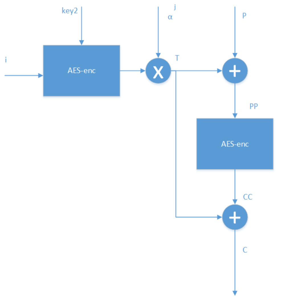
XTS-AES模式主要是解决什么问题,是怎样解决的? XTS-AES模式主要是解决什么问题,是怎样解决的?作者:蒋伟伟链接:https://www.zhihu.com/question/26452995/answer/142440391来源:知乎著作权归作者所有。商业转载请联系作者获得授权,非商业转载请注明出处。XTS即基于XEX(XOR-ENCRYPT-XOR)的密文窃取算法的可调整的密码本模式(Tweakable Codebook mode),该算法主要用于以数据单元(包括扇区、逻辑磁盘块等)为基础结构的存储设备中静止状态数据的加密。以上是官方的解释,谈一下我的理解。我们都知道磁盘上的数据是有一定格式的,比如一个扇区是512字节,磁盘加密直接要对写入扇区的明文进行加密,记录在磁盘扇区上的是相应的密文。而我们通过传统的AES加密方法,比如CBC加密模式,密文须包含一个128bit的初始向量。那么问题来了,我们岂不是要腾出额外的128个bit专门存储初始向量?这样做是增加了磁盘的开销,而且明文和密文在扇区上的存储也不是一一对应的,这给磁盘底层的加密实现带来很大的麻烦。更为关键的是,传统的加密算法,更改密匙非常不便,一旦更改,就意味着要重新进行密匙扩展算法,对磁盘来说要增加很大的开销,同时还要担心密匙泄露的问题。在这种情况下,针对磁盘加密的特点,2002年,Moses Liskov,Ronald L.Rivest, David Wagner,首次提出了可调整的分组密码这个概念,跟传统的分组密码相比,除了密匙和明文这两个输入外,还引入另外一个输入---tweak,即可调整值。这样做的好处是,在不更改密匙的情况下,仅仅改变tweak值,就可以给加密系统提供多变性,既减少了磁盘的开销,也不怕密匙泄露,因为tweak值是公开的,就算泄露了tweak值,如果不知道密匙,是无法破解系统的。而且,这种算法,不需要初始向量,也就避免我们上面所述的明文和密文在扇区上的存储不对应的问题。XTS-AES算法是基于以上思想,被IEEE采用的一个标准。简单介绍下其原理,以传输单个128bit数据块为例:i为128-bit调整值,j为128-bit数据块在数据单元中的位置值,C为128-bit密文数据块。AES-enc为标准AES算法,key2为调整值密匙,key1为数据密匙,模乘操作中 α为GF(2^128)域中对应于多项式x的本源。计算的步骤顺序如下:T <---- AES-enc(key2,i) ⓧ (α^j );PP <----P⊕Thttp://3.CC<---AES-enc(Key1,PP)C<--CC⊕T需要指出的是,j代表数据块在数据单元里的index,比如256个bit数据块,那么 0bit-127bit的j=1,128bit-256bit 的j=2。j 的引入,是让各个数据块的加密保持独立。Disk encryption theoryFrom Wikipedia, the free encyclopediaJump to navigationJump to searchDisk encryption is a special case of data at rest protection when the storage medium is a sector-addressable device (e.g., a hard disk). This article presents cryptographic aspects of the problem. For an overview, see disk encryption. For discussion of different software packages and hardware devices devoted to this problem, see disk encryption software and disk encryption hardware.Contents1Problem definition2Block cipher-based modes2.1Cipher-block chaining (CBC)2.1.1Encrypted salt-sector initialization vector (ESSIV)2.1.2Malleability attack2.2Liskov, Rivest, and Wagner (LRW)2.3Xor–encrypt–xor (XEX)2.3.1XEX-based tweaked-codebook mode with ciphertext stealing (XTS)2.3.2XTS weaknesses2.4CBC–mask–CBC (CMC) and ECB–mask–ECB (EME)3Patents4See also5References6Further reading7External linksProblem definition[edit]Disk encryption methods aim to provide three distinct properties:1.The data on the disk should remain confidential.2.Data retrieval and storage should both be fast operations, no matter where on the disk the data is stored.3.The encryption method should not waste disk space (i.e., the amount of storage used for encrypted data should not be significantly larger than the size of plaintext).The first property requires defining an adversary from whom the data is being kept confidential. The strongest adversaries studied in the field of disk encryption have these abilities:1.they can read the raw contents of the disk at any time;2.they can request the disk to encrypt and store arbitrary files of their choosing;3.and they can modify unused sectors on the disk and then request their decryption.A method provides good confidentiality if the only information such an adversary can determine over time is whether the data in a sector has or has not changed since the last time they looked.The second property requires dividing the disk into several sectors, usually 512 bytes (4096 bits) long, which are encrypted and decrypted independently of each other. In turn, if the data is to stay confidential, the encryption method must be tweakable; no two sectors should be processed in exactly the same way. Otherwise, the adversary could decrypt any sector of the disk by copying it to an unused sector of the disk and requesting its decryption.The third property is generally non-controversial. However, it indirectly prohibits the use of stream ciphers, since stream ciphers require, for their security, that the same initial state not be used twice (which would be the case if a sector is updated with different data); thus this would require an encryption method to store separate initial states for every sector on disk—seemingly a waste of space. The alternative, a block cipher, is limited to a certain block size (usually 128 or 256 bits). Because of this, disk encryption chiefly studies chaining modes, which expand the encryption block length to cover a whole disk sector. The considerations already listed make several well-known chaining modes unsuitable: ECB mode, which cannot be tweaked, and modes that turn block ciphers into stream ciphers, such as the CTR mode.These three properties do not provide any assurance of disk integrity; that is, they don't tell you whether an adversary has been modifying your ciphertext. In part, this is because an absolute assurance of disk integrity is impossible: no matter what, an adversary could always revert the entire disk to a prior state, circumventing any such checks. If some non-absolute level of disk integrity is desired, it can be achieved within the encrypted disk on a file-by-file basis using message authentication codes.Block cipher-based modes[edit]Like most encryption schemes, block cipher-based disk encryption makes use of modes of operation, which allow encrypting larger amounts of data than the ciphers' block-size (typically 128 bits). Modes are therefore rules on how to repeatedly apply the ciphers' single-block operations.Cipher-block chaining (CBC)[edit]Main article: Cipher-block chainingCipher-block chaining (CBC) is a common chaining mode in which the previous block's ciphertext is xored with the current block's plaintext before encryption:Since there isn't a "previous block's ciphertext" for the first block, an initialization vector (IV) must be used as . This, in turn, makes CBC tweakable in some ways.CBC suffers from some problems. For example, if the IVs are predictable, then an adversary may leave a "watermark" on the disk, i.e., store a specially created file or combination of files identifiable even after encryption. The exact method of constructing the watermark depends on the exact function providing the IVs, but the general recipe is to create two encrypted sectors with identical first blocks and ; these two are then related to each other by . Thus the encryption of is identical to the encryption of , leaving a watermark on the disk. The exact pattern of "same-different-same-different" on disk can then be altered to make the watermark unique to a given file.To protect against the watermarking attack, a cipher or a hash function is used to generate the IVs from the key and the current sector number, so that an adversary cannot predict the IVs. In particular, the ESSIV approach uses a block cipher in CTR mode to generate the IVs.Encrypted salt-sector initialization vector (ESSIV)[edit]ESSIV[1] is a method for generating initialization vectors for block encryption to use in disk encryption. The usual methods for generating IVs are predictable sequences of numbers based on, for example, time stamp or sector number, and prevents certain attacks such as a watermarking attack. ESSIV prevents such attacks by generating IVs from a combination of the sector number SN with the hash of the key. It is the combination with the key in form of a hash that makes the IV unpredictable.ESSIV was designed by Clemens Fruhwirth and has been integrated into the Linux kernel since version 2.6.10, though a similar scheme has been used to generate IVs for OpenBSD's swap encryption since 2000.[2]ESSIV is supported as an option by the dm-crypt[3] and FreeOTFE disk encryption systems.Malleability attack[edit]While CBC (with or without ESSIV) ensures confidentiality, it does not ensure integrity of the encrypted data. If the plaintext is known to the adversary, it is possible to change every second plaintext block to a value chosen by the attacker, while the blocks in between are changed to random values. This can be used for practical attacks on disk encryption in CBC or CBC-ESSIV mode.[4]Liskov, Rivest, and Wagner (LRW)[edit]In order to prevent such elaborate attacks, different modes of operation were introduced: tweakable narrow-block encryption (LRW and XEX) and wide-block encryption (CMC and EME).Whereas a purpose of a usual block cipher is to mimic a random permutation for any secret key , the purpose of tweakable encryption is to mimic a random permutation for any secret key and any known tweak . The tweakable narrow-block encryption (LRW)[5] is an instantiation of the mode of operations introduced by Liskov, Rivest, and Wagner[6] (see Theorem 2). This mode uses two keys: is the key for the block cipher and is an additional key of the same size as block. For example, for AES with a 256-bit key, is a 256-bit number and is a 128-bit number. Encrypting block with logical index (tweak) uses the following formula:Here multiplication and addition are performed in the finite field ( for AES). With some precomputation, only a single multiplication per sector is required (note that addition in a binary finite field is a simple bitwise addition, also known as xor): , where are precomputed for all possible values of . This mode of operation needs only a single encryption per block and protects against all the above attacks except a minor leak: if the user changes a single plaintext block in a sector then only a single ciphertext block changes. (Note that this is not the same leak the ECB mode has: with LRW mode equal plaintexts in different positions are encrypted to different ciphertexts.)Some security concerns exist with LRW, and this mode of operation has now been replaced by XTS.LRW is employed by BestCrypt and supported as an option for dm-crypt and FreeOTFE disk encryption systems.Xor–encrypt–xor (XEX)[edit]Main article: Xor–encrypt–xorAnother tweakable encryption mode, XEX (xor–encrypt–xor), was designed by Rogaway[7] to allow efficient processing of consecutive blocks (with respect to the cipher used) within one data unit (e.g., a disk sector). The tweak is represented as a combination of the sector address and index of the block within the sector (the original XEX mode proposed by Rogaway[7] allows several indices). The ciphertext, , is obtained using:where: is the plaintext, is the number of the sector, is the primitive element of defined by polynomial ; i.e., the number 2, is the number of the block within the sector.The basic operations of the LRW mode (AES cipher and Galois field multiplication) are the same as the ones used in the Galois/Counter Mode (GCM), thus permitting a compact implementation of the universal LRW/XEX/GCM hardware.XEX has a weakness.[8]XEX-based tweaked-codebook mode with ciphertext stealing (XTS)[edit]Ciphertext stealing provides support for sectors with size not divisible by block size, for example, 520-byte sectors and 16-byte blocks. XTS-AES was standardized on 2007-12-19[9] as IEEE P1619.[10] The standard supports using a different key for the IV encryption than for the block encryption; this is contrary to the intent of XEX and seems to be rooted in a misinterpretation of the original XEX paper, but does not harm security.11 As a result, users wanting AES-256 and AES-128 encryption must supply 512 bits and 256 bits of key respectively.On January 27, 2010, NIST released Special Publication (SP) 800-38E[12] in final form. SP 800-38E is a recommendation for the XTS-AES mode of operation, as standardized by IEEE Std 1619-2007, for cryptographic modules. The publication approves the XTS-AES mode of the AES algorithm by reference to the IEEE Std 1619-2007, subject to one additional requirement, which limits the maximum size of each encrypted data unit (typically a sector or disk block) to 220 AES blocks. According to SP 800-38E, "In the absence of authentication or access control, XTS-AES provides more protection than the other approved confidentiality-only modes against unauthorized manipulation of the encrypted data."XTS is supported by BestCrypt, Botan, NetBSD's cgd,[13] dm-crypt, FreeOTFE, TrueCrypt, VeraCrypt,[14] DiskCryptor, FreeBSD's geli, OpenBSD softraid disk encryption software, OpenSSL, Mac OS X Lion's FileVault 2, Windows 10's BitLocker[15] and wolfCrypt.XTS weaknesses[edit]XTS mode is susceptible to data manipulation and tampering, and applications must employ measures to detect modifications of data if manipulation and tampering is a concern: "...since there are no authentication tags then any ciphertext (original or modified by attacker) will be decrypted as some plaintext and there is no built-in mechanism to detect alterations. The best that can be done is to ensure that any alteration of the ciphertext will completely randomize the plaintext, and rely on the application that uses this transform to include sufficient redundancy in its plaintext to detect and discard such random plaintexts." This would require maintaining checksums for all data and metadata on disk, as done in ZFS or Btrfs. However, in commonly used file systems such as ext4 and NTFS only metadata is protected against tampering, while the detection of data tampering is non-existent.[16]The mode is susceptible to traffic analysis, replay and randomization attacks on sectors and 16-byte blocks. As a given sector is rewritten, attackers can collect fine-grained (16 byte) ciphertexts, which can be used for analysis or replay attacks (at a 16-byte granularity). It would be possible to define sector-wide block ciphers, unfortunately with degraded performance (see below).[17]CBC–mask–CBC (CMC) and ECB–mask–ECB (EME)[edit]CMC and EME protect even against the minor leak mentioned above for LRW. Unfortunately, the price is a twofold degradation of performance: each block must be encrypted twice; many consider this to be too high a cost, since the same leak on a sector level is unavoidable anyway.CMC, introduced by Halevi and Rogaway, stands for CBC–mask–CBC: the whole sector encrypted in CBC mode (with ), the ciphertext is masked by xoring with , and re-encrypted in CBC mode starting from the last block. When the underlying block cipher is a strong pseudorandom permutation (PRP) then on the sector level the scheme is a tweakable PRP. One problem is that in order to decrypt one must sequentially pass over all the data twice.In order to solve this problem, Halevi and Rogaway introduced a parallelizable variant called EME (ECB–mask–ECB). It works in the following way:the plaintexts are xored with , shifted by different amount to the left, and are encrypted: ;the mask is calculated: , where and ;intermediate ciphertexts are masked: for and ;the final ciphertexts are calculated: for .Note that unlike LRW and CMC there is only a single key .CMC and EME were considered for standardization by SISWG. EME is patented, and so is not favored to be a primary supported mode.[18]Patents[edit]While the authenticated encryption scheme IAPM provides encryption as well as an authentication tag, the encryption component of the IAPM mode completely describes the LRW and XEX schemes above, and hence XTS without the ciphertext stealing aspect. This is described in detail in Figures 8 and 5 of the US patent 6,963,976.[19]See also[edit]Data remanenceCold boot attackDisk encryption softwareDisk encryption hardwareIEEE P1619, standardization project for encryption of the storage dataReferences[edit]1.^ Clemens Fruhwirth (July 18, 2005). "New Methods in Hard Disk Encryption" (PDF). Institute for Computer Languages: Theory and Logic Group (PDF). Vienna University of Technology.2.^ "Encrypting Virtual Memory" (Postscript).3.^ Milan Broz. "DMCrypt dm-crypt: Linux kernel device-mapper crypto target". gitlab.com. Retrieved April 5, 2015.4.^ Jakob Lell (2013-12-22). "Practical malleability attack against CBC-encrypted LUKS partitions".5.^ Latest SISWG and IEEE P1619 drafts and meeting information are on the P1619 home page [1].6.^ M. Liskov, R. Rivest, and D. Wagner. Tweakable block ciphers [2], CRYPTO '02 (LNCS, volume 2442), 2002.7.^ Jump up to:a b c Rogaway, Phillip (2004-09-24). "Efficient Instantiations of Tweakable Blockciphers and Refinements to Modes OCB and PMAC" (PDF). Dept. Of Computer Science(PDF). University of California, Davis.8.^ https://link.springer.com/content/pdf/10.1007/978-3-540-74462-7_8.pdf section 4.1.9.^ Karen McCabe (19 December 2007). "IEEE Approves Standards for Data Encryption". IEEE Standards Association. Archived from the original on 2008-03-06.10.^ Standard for Cryptographic Protection of Data on Block-Oriented Storage Devices. IEEE Xplore Digital Library. April 18, 2008. doi:10.1109/IEEESTD.2008.4493450. ISBN 978-0-7381-5363-6.11.^ Liskov, Moses; Minematsu, Kazuhiko (2008-09-02). "Comments on XTS-AES" (PDF)., On the Use of Two Keys, pp. 1–3.12.^ Morris Dworkin (January 2010). "Recommendation for Block Cipher Modes of Operation: The XTS-AES Mode for Confidentiality on Storage Devices" (PDF). NIST Special Publication 800-38E. National Institute of Standards and Technology.13.^ "NetBSD cryptographic disk driver".14.^ "Modes of Operation". VeraCrypt Documentation. IDRIX. Retrieved 2017-10-13.15.^ "What's new in BitLocker?". November 12, 2015. Retrieved 2015-11-15.16.^ Standard for Cryptographic Protection of Data on Block-Oriented Storage Devices (PDF), IEEE P1619/D16, 2007, p. 34, archived from the original (PDF) on 14 April 2016, retrieved 14 September 201217.^ Thomas Ptacek; Erin Ptacek (2014-04-30). "You Don't Want XTS".18.^ P. Rogaway, Block cipher mode of operation for constructing a wide-blocksize block cipher from a conventional block cipher, US Patent Application 20040131182 A1.19.^ * U.S. Patent 6,963,976, "Symmetric Key Authenticated Encryption Schemes" (filed Nov. 2000, issued Nov. 2005, expires 25 Nov. 2022) 3.Further reading[edit]S. Halevi and P. Rogaway, A Tweakable Enciphering Mode, CRYPTO '03 (LNCS, volume 2729), 2003.S. Halevi and P. Rogaway, A Parallelizable Enciphering Mode [5], 2003.Standard Architecture for Encrypted Shared Storage Media, IEEE Project 1619 (P1619), [6].SISWG, Draft Proposal for Key Backup Format [7], 2004.SISWG, Draft Proposal for Tweakable Wide-block Encryption [8], 2004.James Hughes, Encrypted Storage — Challenges and Methods [9]J. Alex Halderman, Seth D. Schoen, Nadia Heninger, William Clarkson, William Paul, Joseph A. Calandrino, Ariel J. Feldman, Jacob Appelbaum, and Edward W. Felten (2008-02-21). "Lest We Remember: Cold Boot Attacks on Encryption Keys" (PDF). Princeton University. Archived from the original (PDF) on 2008-05-14.Niels Fergusson (August 2006). "AES-CBC + Elephant Diffuser: A Disk Encryption Algorithm for Windows Vista" (PDF). Microsoft.External links[edit]Security in Storage Working Group SISWG."The eSTREAM project". Retrieved 2010-03-28.
-
浅谈芯片的bringup 一,浅谈芯片研发谈到芯片,中美贸易战的中兴事件引发了社会对芯片行业的大量关注,本文不做累述芯片行业现状、痛点,只给大家展现芯片行业纯技术的某一面。先以芯片研发流程开篇,下图为个人理解的芯片研发流程图。图1 芯片研发流程图任何产品都有面向群体,芯片也不例外,面向手机、相机等消费类电子产品,面向机器人、行业自动化等工控类设备,目前主流芯片偏向消费类电子。芯片的面向最终都是转换成规格和需求,需求方或领导层先提要求,架构工程师、项目经理、项目管理、各技术组组长坐在一起讨论拍板出我们芯片所需要的规格list和需求list,这是第一步。接着,项目管理、经理负责资源组和人员的调配。技术方面,架构师是重点,对需求和规格list进行细化到具体,搭建架构,架构的分析与建模,仿真出可行性,比如整个集成芯片划分为几个模块、CPU选型、主频、总线划分等。如果涉及到高层次算法,需要完成芯片中数字部分的高层次算法,为硬件提供一个正确的软件功能模型,通过大量的高层次仿真和调试,为RTL实现提供总体性的设计指导。芯片从功能上来看,是由各个IP综合集成出来的。国内多数集成芯片都是采购IP,自研IP多数为小IP,一般ARM、DSP、普罗米修斯等CPU类IP多为采购,当然也不乏大公司自研DSP、超级CPU等,DDR PHY、SD PHY等高速接口IP也多为采购,国内算法能力很强,目前ISP、GPU、CNN、CODEC等都有大公司在自研。集成和实现都是RTL阶段,CRG(Clock Reset Gate)就是在这个阶段设计的,另外系统、总线、安全等相关控制也是RTL集成和实现的重点。集成将所有IP集合,安排和分配好脉搏、功能信号。实现靠近实际,RTL实现之后就是软件人员所看到的寄存器手册。集成阶段非常重要的是时序,尤其是异步时序,所以需要验证。验证由根据平台划分为EDA验证、FPGA验证、ZEBU验证等。嵌入式接触比较多的是FPGA和ZEBU验证。EDA验证是模拟的环境上验证的,但其最接近最后的AISC,但仿真毕竟是仿真,离实际差异还是很大;FPGA只能做前端验证,它最真实,也是验证速度最快的,但其频率的限制、模拟器件无法模拟,导致很多功能并不能验证的很完整,CRG 、power control、pinmux根本无法验证,,各类高速接口的PHY无法真实测试,FPGA的CRG一般尽量按比例集成;ZEBU平台也是基于FPGA上集成的,但其可完全模拟出时序关系,不过也存在FPGA的其它通病,而且其验证速度比EDA更慢,跑一个复杂点的验证用例可能需要一天。各大仿真或验证平台各有优缺点,但实际的芯片并没有验证环境那么理想,有corner、生产工艺、功耗散热、DDR稳定性等各种因素,导致最后的芯片问题百出。需要注意,验证并不是固定顺序的,任何一个阶段都需要。前面陈述的都属于前端,国内后端不甚重视,总体上按顺序有数据整理提供、布图、布局、preCTS(setup优化)、CTS(clock tree setup)、postCTS(进一步优化)、布线、post布线、ECO(进入此过程再无法修改数据)、finish、signoff(检查和验证)、tapeout(设计数据传递给制造方)。最后就是流片生产,多数在台积电、台联电,嵌入式在此过程需要准备回片bring up的代码,重点在CRG、power、高速IP等仿真无法覆盖完整的代码。然后等芯片回来,芯片一旦回来,就是嵌入式的大头戏,回片bring up阶段,所有人都在关注着这最后一炮的成功与否,芯片就是一锤子买卖,题外话的说,芯片的回片现场非常类似robocon比赛现场。以下以常用的ARM cortex-A为主的SOC系列芯片bring up为例。本文纯手敲,如有出入,自行参考。二,整体bring up流程回片bring up工作非常关键,但芯片是否如意并不是嵌入式能决定的,虽然前期有负责FPGA、ZEBU验证起到验证作用,但芯片行业的核心不在嵌入式,我们只是检验大家成果的一面镜子。但换个方向思考,嵌入式是处于最底层的软件,对芯片负责,如果过了嵌入式把问题释放出去,那就会收到无数的投诉、黑评等。回片工作流程如图2。图2 芯片回片bring up流程回片工作基本上所有IP的冒烟都需要两个前提,coresight(debug/trace)和DDR。图2中还少了SOC的基本功能冒烟实现这个前提,比如CRG、power manager、安全等,由于其牵涉到每一模块,故不加入图中。DDR冒烟非常关键,通常三大巨头公司海力士、镁光和三星都需要测试,开始时有bypass training方案,高频方案等,与产品实际性能需求有关,后面为了稳定性还得进行不同corner芯片、高低温下的压力测试。DDR之后就可以并行工作了,此时需要根据芯片应用场景进行对应IP功能冒烟,图2提供了多种场景的bring up实现,最基础的kernel的启动、sensor-显示通路、图像识别和处理、编解码等。本文重心在系统的bring up介绍,不展开场景介绍。三,系统的bring up系统的启动流程是bootrom->bootloader->kernel->filesystem,具体可参考图3。图3 某芯片启动流程详解图1,bootrombootrom是系统之始,也就是第一份代码,例如BIOS就是windows的bootrom。大部分嵌入式开发者或者谷歌BSP(Board Support Package)一般最多深究到bootloader,忽略bootrom也是因为它是随着生产固化的,与芯片本身息息相关,硬件工程师关注比较多,软件不可更改,也没必要修改。但如果想对芯片真正了解,必须对bootrom的代码甚为了解。bootrom里面做了以下几个事:(1)主CPU boot,一般bootrom只启动单核,并配置处于次低频态;(2)切入slow或normal模式;(3)efuse相关位检测;(4)如果涉及到,调整芯片的安全相关属性;(5)如果涉及到,将必须的电压打开;(6)配置debug串口,提供开发者调试;(7)检测是否非默认引导方式,并引导,有flash/emmc、USB fastboot、ETH等引导;(8)根据所选方式引导,跳转到RAM起始地址。值得注意的是既然有多种引导方式,那就可以用以太网、USB甚至串口传输boot程序给芯片,让其运行自己想要的非主线分支程序,比如fastboot功能的实现、安全属性强行修改等。当然,芯片安全问题不用担心,efuse里会有加密信息,bootrom会去校验你的FW,俗称签名。2,bootloaderbootloader非常关键,是底层软件大展身手的地方。bootloader最终目的是启动内核,至于内核是linux、rtos或者其它OS都可以。bootloader也并不止uboot,还有little kernel、redboot、armboot等,甚至可以自己手写,个人接触比较多的是uboot和little kernel。uboot适应性高,对成熟芯片可以做到是快速上板,对新开发芯片能做到参考作用,但其内容繁琐,全新芯片开发难度比little kernel更大。此处以更为通用的uboot展开,讲述bootloader具体干了什么事情。Uboot,即universal-bootloader,分为两个阶段,SPL阶段和uboot第二阶段,划分两个阶段是因为片内RAM的价格高昂,且大小一般都只有几十上百K。uboot为了适应各种平台适应各种OS,越到后面版本越来越庞大,为此设计者将uboot一分为二,将初始化flash/emmc并把存储的程序搬运到片外RAM的小uboot称为SPL,将启动内核的大uboot放入片外RAM(一般是DDR,即SDRAM),采取图4流程启动OS。Uboot也支持单阶段启动或者直接flash启动,但都非常少用,个人曾强行简化uboot到100K,但把uboot很多模块给去除了,比如交互界面、哈希表,导致代码完全像重写,后面弃用不了了之。图4 uboot启动流程图4是常见的一种uboot流程,由于是两片内存空间,两个阶段都需要做系统的初始化工作,异常向量表、堆栈、BSS、data、heap、代码段,值得重视的是SPL在底层初始化阶段是无BSS、data、heap段的。SPL阶段的流程很简单:(1)ARM的boot,SP、exception设置,关闭MMU、Icache、Dcache;(2)初始化CRG,电压、频点和工作模式初始化;(3)初始化debug串口,初始化FLASH,初始化片外RAM;(4)如果有需要,release其它核或其他CPU,如DSP、cortex-M系列ARM等;(5)如果有安全需要,boot TrustZone OS;(6)Relocate堆栈、GB等到第二阶段uboot;(7)直接跳转到片外RAM执行第二阶段。第二阶段就是uboot真正起作用的阶段了,其主要流程见图5。uboot的核心在于boot起各类kernel,但它本身不止于此,它还有改写flash内容,对内存映射区域改写,修改启动环境参数等功能,实现都在图5的最后console界面里,俨然是一个小型的裸机交互系统。图5 第二阶段uboot流程这里只浅谈下核心部分,也就是起kernel功能。uboot启动的内核为uImage或者zImage,也可以是压缩包,内核格式一般是由两部分组成:真正的内核和内核头部组成,头部中包括内核中的一些信息,比如内核的种类,加载地址,入口地址。以linux为例:uboot在接收到启动命令后,要做的主要是,读取内核头部信息,移动内核到合适的加载地址,启动内核,执行do_bootm_linux。do_bootm_linux主要做的为,设置启动参数,在特定的地址,保存启动参数arg,传递设备树dtb,以及根文件系统rootfs信息,解压kernel并放置到指定片外RAM位置,跳到入口地址,启动内核。3,Kernel大部分嵌入式都是在kernel之上做着辛勤的工作,调用各种标准的写驱动接口,基于各种驱动做开发,标准的代码接口,比如linux的io control、debugfs、sysfs、用户态程序,再如rtos的任务创建挂起、信号量、邮箱等等。本节非常浅面的谈谈kernel的bring up过程。以linux为例,主要流程如图6。图6 linux启动流程首先,从bootloader接管控制权后,首先读入根目录下的内核文件,该过程对设备树进行了扫描注册。内核文件加载以后,就开始运行第一个程序linuxrc或init,它的作用是初始化系统环境,这个进程的PID为1,后面称之为init进程。这时候,许多程序需要开机启动,这些在Windows叫做“服务”(service),在Linux就叫做"守护进程"(daemon),init进程的一大任务,就是去运行这些开机启动的程序。但是,不同的场合需要启动不同的程序,linux允许为不同的场合,分配不同的开机启动程序,这就叫做“运行级别”(runlevel)。接着,每个运行级别的运行程序在/etc目录下面,都有一个对应的子目录rc*.d,选择后通过init.d链接启动。这时,开机启动程序加载完毕,然后要让用户登录,有三种登陆方式:命令行登录、ssh登录和图形界面登录,为了方便一般用ssh登录或者直接默认登录某user用户来方便开发者调试。至此,Linux的启动过程就算结束了。4,filesystem文件系统的格式极其多,每种格式都有独立的生成标准,最常用的格式,ext4、fat32,一个是linux常用,一个是windows常用,占了大片江山。所有格式文件系统说白了都是对操作系统用于在存储介质上组织文件的方法。存储设备不管是易失的RAM,还是不丢失的ROM,只要可以提供标准的initialization、read、write,都可以对某个区域或者整个区域进行格式化。比较常见的文件系统格式化设备有SD卡、硬盘、EMMC等ROM设备,一般不用于RAM中。rtos一般是等系统起来后通过进程去管理文件系统,不会用到RAM文件系统。但linux不同,在boot loader 配置了某些参数的情况下(这也是常规做法),它的启动不会一来就加载ROM的文件系统,这就涉及到一个中间系统,称为initrd、ramdisk或者initramfs,后面简称initrd。而最后我们敲shell命令的界面所在文件系统称作rootfs,也即根文件系统。以下浅要介绍linux启动所用的到文件系统。在linux内核启动前,boot loader 会将存储介质中的initrd文件加载到片外RAM,内核启动时会在访问真正的根文件系统前先访问该内存中的initrd 文件系统。内核启动被分成了两个阶段,第一阶段先执行initrd 文件系统中的某个初始化文件,完成加载驱动模块等任务,第二阶段才会执行真正的根文件系统(rootfs)中的init 进程。linux是基于unix的系统,unix的设计之初有一哲学核心思想,即“一切皆文件”,在linux上的体现就是rootfs。简单的说,rootfs是一个带有linux整套内核体系结构和硬件设备注册的文件系统,可以看到设备节点,用户进程,debug信息等。相信linux驱动工程师了如指掌。不管是rootfs还是initrd,其实都是一样的文件形式,可以做成同源。rootfs的生成比较有名的工具叫做busybox,busybox自带有许多设备操作和shell的库。在这介绍两个开源代码,一个叫做buildroot,一个叫做yocto,都是基于busybox工具上的rootfs生成项目,都具备可视化可裁剪定制界面,库自选,busybox还带有许多boot kernel相关开源代码,同样initrd也可通过它们获得。至此,芯片的系统bring up结束。接下来就是各模块的驱动开发,和各种业务场景的实现了。版权声明:本文来源网络,免费传达知识,版权归原作者所有。如涉及作品版权问题,请联系我进行删除。https://www.eet-china.com/mp/a350381.html